
Description
Merk: 3B SCIENTIFIC
Objective Determine the value of certain resistances
Summary
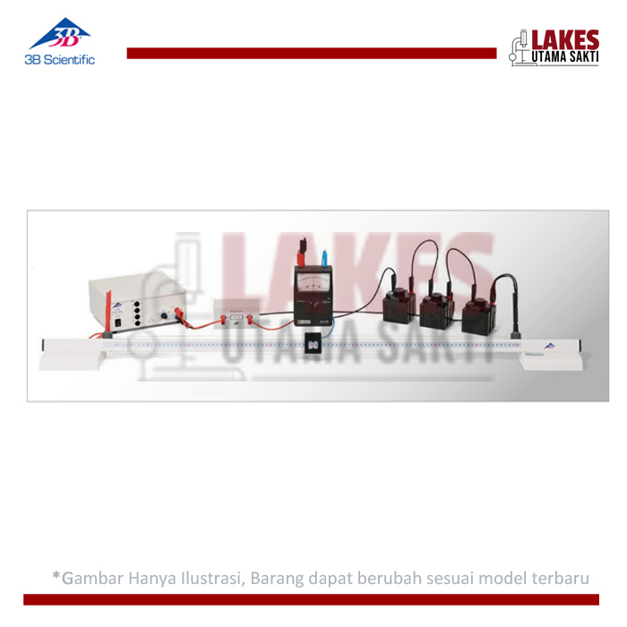
An arrangement in which two voltage dividers are connected in parallel and connected to the same DC voltage source can be used to obtain the values of certain resistors. The first voltage divider consists of the resistance that is to be measured along with a reference resistance, while the second consists of a resistance wire 1 m in length that is divided into two sections by a sliding contact. The ratio between the two sections is adjusted until the current across the diagonal between the two voltage dividers becomes zero. Experiment Procedure • Determine resistances using a Wheatstone Bridge. • Estimate the accuracy of the measurements.
Required Apparatus
1 Resistance Bridge [1009885]
1 AC/DC Power Supply 0 – 12 V, 3 A @230 V [1021091]
1 Zero Point Galvanometer CA 403 [1002726]
1 Resistance Decade 100 Ω [1002732]
1 Resistance Decade 1 kΩ [1002733]
1 Resistance Decade 10 kΩ [1002734]
1 Precision Resistor 100 Ω [1009886]
1 Precision Resistor 1 kΩ [1009887]
1 Set of 15 Safety Experiment Leads, 75 cm [1002843]
Basic Principles A classical method for measuring resistances uses a voltage balancing bridge named after Charles Wheatstone to compare the unknown resistance with a reference resistance. This involves setting up a circuit consisting of two voltage dividers in parallel, with a single DC voltage source connected across the whole. The first voltage divider consists of the resistance Rx that is to be measured and a reference resistance Rref, while the second consists of two resistances R1 and R2, the sum of which remains constant during the balancing process.

